|
My research interests include the behavior of concrete structures under static and cyclic loading, composites material in civil engineering and nonlinear dynamic analysis of concrete structures, elevated tanks, steel structures, shear wall and concrete composite shells. my research focuses on the lap-spliced length in plan and steel fiber reinforced concrete. Other research interest include simulation in ABAQUS finite element software.
Some of results have been obtained as follow:
Investigation the behavior of steel fibers reinforced concrete beams with lap-spliced bars
In reinforced concrete structures, sufficient anchorage length in the connections and lap-spliced bars are essential and of great importance. steel and synthetic fibers were used to enhance the properties and performance of concrete. Fibers interact with the matrix at the level of micro-cracks and effectively bridge these cracks and delays their unstable growth in the hardened state and when fibers are properly bonded. An increase in the tensile strength of the concrete can be observed when the fiber volume fraction is sufficiently high. Once the maximum tensile capacity of the composite is reached, and coalescence and conversion of micro-cracks to macro-cracks has occurred, fibers continue to restrain crack opening and crack growth by effectively bridging across macro-cracks, depending on their length and bonding characteristics. Steel fibers are used mostly in columns and beams under moment and shear stress. FRC are used most widely and reliably in the practical fields, particularly for tunnel shotcrete and precast tunnel segments as well as in industrial pavement and slabs.
In FRCs with low to medium fraction of fibers, fibers do not enhance the tensile and flexural strength of the composite. In these types of concrete, benefits of fiber reinforcement are only limited to energy absorption or ‘toughness ‘enhancement in the post-cracking regime. For FRCs with a high fiber percentage, benefits of fiber reinforcement are seen as an increased tensile strength, strain-hardening response before localization and enhanced ‘toughness ‘beyond crack localization [19]. the presence of the steel fibers causes improved performance of the flexural member when the specimen with fibers is subjected to bending. Use of fibers at the cracking location causes delay in crack extension.
While designing the FRC structures, the tensile performance is commonly measured using the equivalent flexural ratio. In concrete structures, RC specimens which are incorporated with steel fibers, have an enhanced bonding mechanism since the steel fibers cause crack opening to delay and exert tensile strength after onset of cracking [22]. In reinforced concrete beams the addition of steel fibers in concrete also seems to improve the behavior of lap-spliced bars.
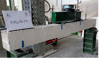
Beam specimens were manufactured using concrete with the admixture of steel fibers. The steel fibers are normally used in reinforced concrete members to increase flexural strength, reduce crack widths, and increase resistance against impact loading. This research investigates the behavior of fiber reinforced concrete beams with lap-spliced bars. The lap-spliced bars and flexural ductility of these beams are the main objectives of the research.
The beam with a 2300mm span was supported by round bars and two concentrated line loads were applied as follow.
 . .
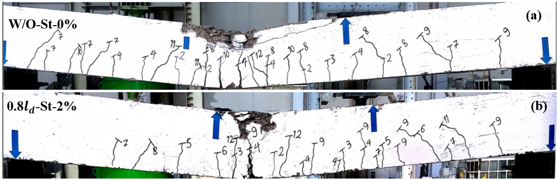
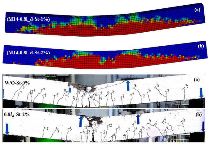
According to below Figure, the flexural cracking of two specimens are shown. the crack width was significant improved by using steel fibers in reinforced concrete beams with lap-spliced bars.
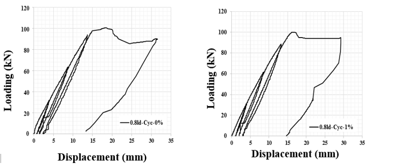
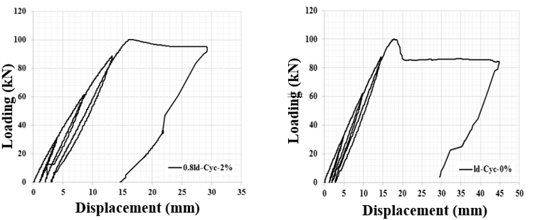
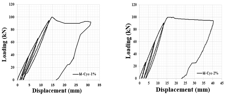
Cyclic loading was applied with the displacement interval of until failure of the specimen. The test results of the specimens subjected to cyclic loading are shown in following Figure.
Based on the result of the test, the following conclusion are drawn:
- By addition of steel fibers with a volumetric percentage of 2 to the reinforced concrete beams with lap-spliced bars, the splice length could be reduced at least 20% without reduction in the strength and ductility of beams.
- The specimens with lap-spliced bars and 1% or 2% steel fibers have greater ductility ratios compared with the control specimen without lap-spliced bars.
- with the addition of steel fibers and increase coherence between rebars and concrete cracking is less developed. So, beams with 2% steel fibers deformed with more ductility and didn’t collapse suddenly
Investigation the behavior of steel fibers reinforced concrete beams with lap-spliced bars
In addition to providing a sufficient flexural strength, concrete beams ductility should be well-provided and not suddenly destroyed. Various parameters affect the ductility of reinforced concrete beams with lap-spliced length. The cross-section reinforcement ratio, concrete cover, lap-spliced length, percentage of steel fibers and concrete compressive strength are the parameters influencing the ductility of steel fibers reinforced concrete beams with lap-spliced length.
In reinforced concrete beams, in addition to providing flexural strength, appropriate cross-section reinforcement ratio has to provide that the beam is not suddenly damaged and degraded by deformation and warning. In reinforced concrete beams with lap-spliced length, the length of the lap-spliced must be determined to a degree that, in addition to the bonding and supply of flexural strength, ductility of the beam is also provided. The bond between reinforcement and concrete is one of the most important parameters in RC concrete beams. The lap-spliced bonding in reinforced concrete beams depend on cross-section reinforcement ratio, embed high, reinforcement diameter, the strength of the concrete and loading.
Increasing the transverse reinforcement along the lap-spliced length, in addition to providing a brittle failure in the lap-spliced length interval, prevents the expansion of crack widths. So, flexural capacity improved due to increase bond strength. According to the studies, various relations have been presented by the researchers. Regulations have also proposed relationships for predicting lap-spliced length. The ductility of RC concrete beams is ensured when the ratio of the reinforcement ρ is less than the maximum value of the reinforcement ratio. Results showed that the proposed relationship by ACI 318-95 does not provide ductility. Hence, according to the study, it was suggested that more transversal reinforcement be applied over the lap-spliced length.
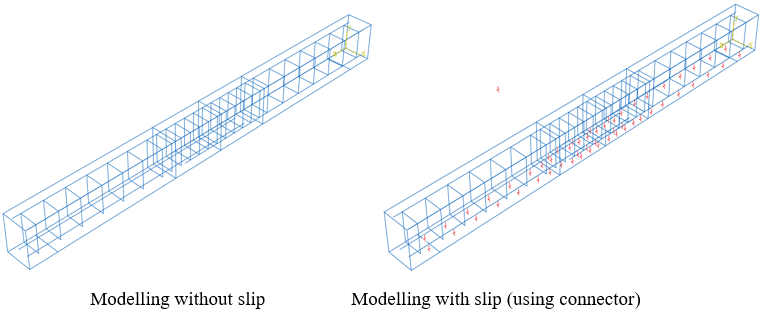
According to the results of laboratory tests and specifications of materials, the modeling was done in ABAQUS software.in following figures are represented modelling with slip (with connector) and without slip.
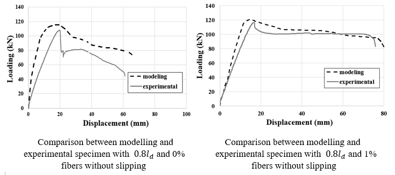
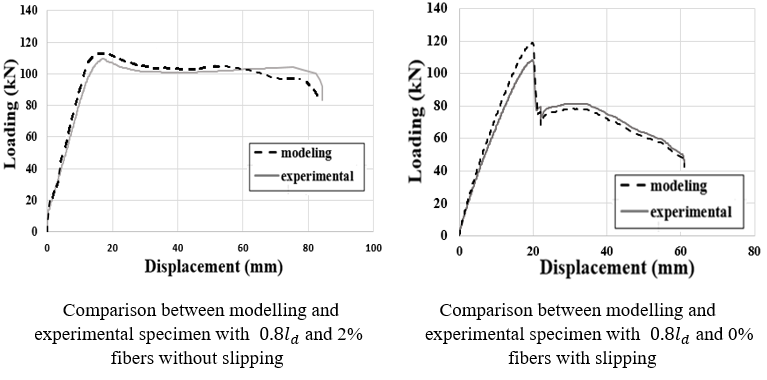
To do the modeling, firstly, the analyzed model in the software is verified with the results of experimental specimens. In below figures, the result of the comparison of the displacement loading diagram of the laboratory sample with a modelling are represented.
According to experimental specimens and modeling, the effect of increasing effect of cross-section reinforcement ratio, the percentage of steel fibers and lap-spliced length on the behavior of specimens was investigated. in the following figures, cracking is shown in modelling and experimental specimens, respectively.
In this research, the effect of different parameters as cross-section reinforcement ratio, the percentage of steel fibers and lap-spliced length on the ductility ratio was investigated. The effect of steel fiber on flexural strength and ductility of the spliced reinforced concrete beams with the effect of slipping interaction in modeling are the main objectives of the research. Based on the result of the test, the following conclusion are drawn:
1- In the modelling reinforced concrete beam with lap-spliced length must modelling slipping effect by using connector with axial and flexural behavior. By using this type of connector could be obtained accurate results with good agreement with experimental results.
2- In steel fibers reinforced concrete with more than 1 percentage volume could be ignored slipping and using embed interaction between reinforcement and concrete.
3- it was found that by addition of steel fibers with a volumetric percentage of 2 to the specimen, the lap-spliced bars could be reduced at least 40%, without reduction in the strength and ductility.
4- Based on the obtained results, the FE model developed has successfully simulated the bond-slip obtained through experimental test for steel fibers reinforced concrete beams without and with lap-spliced bars.
Prediction Flexural crack width of fiber reinforced concrete beams with lap-spliced under cyclic loading using neural network
Crack spacing reduction is one of the important parameters in protecting reinforcement corrosion. There is variable method for crack spacing prediction. Influence of various parameters on cracking. Concrete cover, concrete compressive strength, size and spacing of longitudinal and transverse reinforcement of the parameters affecting crack spacing of bending. The use of insufficient lap-spliced to reduce capacity and increase the crack spacing in reinforced concrete beams.
Lack of tension strength of concrete members, due penetration chemicals material in this members. This can cause rust and corrosion of reinforcement. Some researches has done for prediction flexural crack spacing in concrete members. Plastic Truss theory most complete method to determine the strain and crack spacing in reinforcement concrete members under combined loading. The results shown that the compressive strength and thickness of section have minimum effect on crack spacing. Erosion rate is the most important affecting factor on the spread of crack spacing. Various methods for determining crack spacing in reinforced concrete members under bending load combinations suggested. In experimental studies, mid-span deformation of beam and crack spacing in reinforced with GFRP bars were examined. In reinforced concrete member. GB50010 modified method to predict the flexural crack spacing of reinforced concrete beams reinforced with FRP rebar is used. Some experimental methods to determine the maximum flexural cracks spacing in reinforced concrete beams with FRP rebar was obtained. Strain mixture model for concrete under tension members suggested. With the energy equivalent method, a simple equation to determine the fracture strain and fracture energy of concrete is expressed as a function . Also, Analytical model for estimating crack spacing due to erosion model offered.
For calculation crack spacing and its spacing can use two dimensional finite element analysis. Crack spacing and propagation crack in reinforced concrete beams with different longitudinal reinforcement ratio can be analyzed in self-compacting concrete. The numerical model used to calculate the spacing of the cracks in the concrete Prestressed Concrete Association members under bending is provided. crack spacing in reinforced concrete members with different arrangement of sections and longitudinal reinforcement can calculate using this model. A high-precision digital system determining the flexural crack spacing in reinforced concrete members provided.
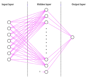
Neural network used to predict pre-fabricated concrete beam flexural crack spacing. By this method can be extended diagonal crack spacing in reinforced concrete beams will also be determined. Some Studies on the use of neural network to estimate the cracking of the concrete members has been done. The structure of neural network consists of three parts: input, hidden and output layers as shown in following figure. The hidden layer with appropriate training input to output relationship is obtained. Given the complexity of inputs and outputs are suitable conversion solution may be hidden layer to the substrate becomes hidden
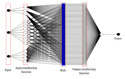
Adaptive neuro fuzzy inference (ANFIS) and neural network are methods that can be used to prediction a phenomenon. ANFIS a neuro-fuzzy neural network based on Takagi-Sugeno. It was created in the early 1990s. This system is used for prediction. How to work an envelope is that by generating a dataset and importing it into the enfaces, this program finds out the training and the relationship between the output and the inputs. In the next step, and after learning it by entering any input, the encipher predicts the output values. these values are determined by trying and error. The structures used to solve the problem is shown in below figure.
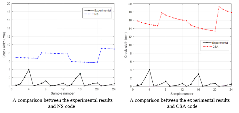
Neural networks and Adaptive neuro fuzzy inference system is used to predict the cracking spacing. The results of the experimental results with codes like CSA-2004, NS-1992, EC2-2004, CEB-FIP-1990 and ACI 224R-2001 has been compared. Results is shown in following fogures. According to Figs 16 and 20 codes equation can calculate crack spacing properly and overdesign.
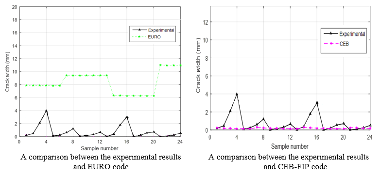
In this study, crack spacing in lap-spliced steel fiber reinforced concrete beam under cyclic loading was investigated using neural network and Adaptive neuro fuzzy inference. According to the results of 20 steel fiber reinforced concrete beam lap-spliced under cyclic loading to compare the predicted with the proposed Regulations relations were discussed. So, the following results were obtained
- neural network and Adaptive neuro fuzzy inference are useful tools in predicting cracking spacing. By comparing these methods with the introduced cods show the ability of this method to predict the crack spacing according to the results of the tests
- with comparing the results with different cods, it became clear that ACI 224R-200 can offer a good estimation of crack spacing in lap-spliced steel fiber reinforced concrete beam under cyclic loading. This is while, CSA-2004, NS-1992, EC2-2004 spacing of cracking as reliable and CEB-FIP-1990 for unsafe forecast
- the effect of lap-spliced bars and steel fibers in fiber reinforced concrete beams with lap-spliced length are obvious and available relationship for determining crack spacing are poor.
- the available equation in codes only considered the most important parameters, such as rebar spacing, rebar diameter, concrete cover and environmental condition, although, in concrete beams with lap-spliced bars and steel fibers must consider the effect of amount of steel fibers and lap-spliced length
The Effect of polypropylene fibers on the mechanical behavior of self-compacting concrete
The self-compacting concrete can be used for concrete members which can’t compact good. Lack of appropriate compacting can be caused varies reasons as high volume of concrete, lack of proper space for vibration and etc. For obtaining self-compacting concrete, using an appropriate mix design is important. The mechanical properties of SCC reduce exposed to impact loading and heat. By increasing cracks, the concrete can’t endure loading and fracture suddenly.
The PPF are obtained from monomeric C3H6 that is purely hydrocarbon. According to its PPF regular structures properties, it is observance as isotactic polypropylene. Also, its fibers resistant to chemicals. The hydrophobic surface not being wet by cement paste helps to prevent chopped fibers from balling effect during mixing like other fibers. The fibers are manufactured by the pulling wire procedure with circular cross section or by extruding the plastic film with rectangular cross-section. So, PPF caused tensile strength and continuity between concrete components (cement and aggregated) increased and the behavior of SCC can be improved. PPF considerable can be reduced shrinkage cracking. Therefore, PPF can be improved the toughness, ductility, impact resistance, tensile and compressive strength of concrete, another area of using PPF are in pavement slabs, pile shells, concrete filled section, shotcrete for concrete tunnel, channels and reservoirs. As mentioned earlier, several researchers have reported the preventative effect of PPF against impact loading and heating.
The weight drop test is used to assess the impact strength . In studies on fiber-reinforced concrete with high strength, the results showed that the number of impacts that cause the first cracks in the sample are very different. According to previous results, the optimal energy absorption of concrete was obtained by adding 1 percent volume of polypropylene fibers in interval between 0 to 1% . By conducting further studies on fiber-reinforced beams, a new impact test method was proposed. In this method, by creating a cut in the lower part of the beams, the place of occurrence and the beginning of the cracking were determined and by calculating the energy of impacts, various specimens were examined .
Increasing the temperature reduces the strength of the concrete. The phenomenon of scattering and separation of surface aggregates of concrete, the impossibility of water vapor leaving the concrete, and as a result of increasing internal pressure, are the main causes of the decrease in concrete strength at high temperatures. Since the 1980s, many studies have focused on the effects of high temperatures on the behavior of fiber concrete. These studies showed that, as the temperature rises, the occurrence of the scaling phenomenon in concrete would be rapid. Investigations on load-displacement curves of high-strength concrete specimens under direct fire influence indicate that concrete properties will be significantly changed after being exposed to fire. According to the United States Standard and Technology Association studies, the effect of high temperatures on mechanical properties was investigated. According to results by increasing temperature, the mechanical properties of concrete was reduced.
The results of previous studies shown that using PPF, the mechanical and physical behavior of SCC was improved. Up to now, various mix design of SCC was presented and the SCC behavior was investigated by adding the different amount of fibers as polypropylene, steel and etc.
In this study, the Effect of polypropylene fibers on the strength, impact and heat resistance of SCC. Part of the innovation of this research lies in using quick setting cement in mixtures. Also, the mechanical behavior of SCC was investigated in specimens without and with PPF before and after heating. Therefore, the effect of heat was studied in this research.
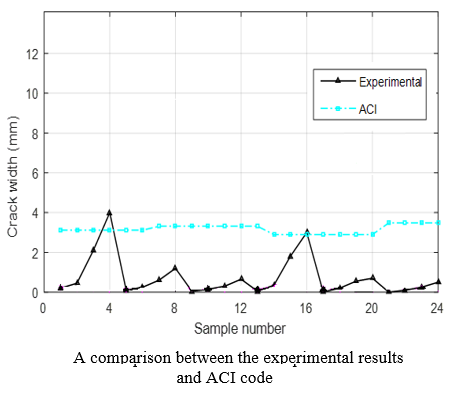
the location of the first cracks and the breakdown pattern of the (SP1W2H0.5)1 specimen in the impact resistance test is shown in following figure. The drop weight impact was performed on 30 rectangular cube specimens using two kinds of the spherical metal ball with masses of 520 and 920 grams and different fall height, 0.5 m and 1 m. Increasing height of the fall and ball weight caused to decrease the number of the blow to create the first crack and the complete failure. According to the results, the number of the blow to create the first crack and the complete failure increased with increasing the PPF addition.
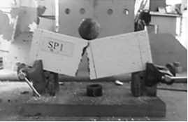
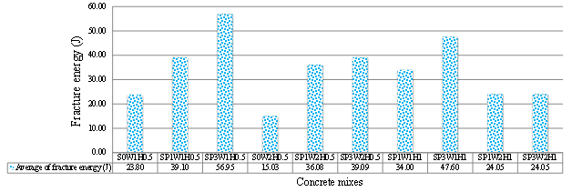
Increasing high of fall and ball weight caused to increase fracture energy. Also, using fibers as well as increase fracture energy. So, in different specimens, fracture energy will be difference.
The fracture energy was increased due to increase the percentage of polypropylene fiber. So the first crack and ultimate fracture in specimens need more number of blow against the control specimen (without polypropylene fiber). Also, the effect of changing high is more than the effect of changing weight balls.
Based on the result of the test, the following conclusion are drawn:
- By increasing the fiber percentage, the amount of diameter of the slump reduced, Substantially. The diameter of the slump flow from 650 mm in a control specimen without polypropylene fibers is changed to 490 mm in a sample containing 0.1% volumetric fibers and 300 mm in a sample containing 0.3% volumetric fiber.
- The presence of polypropylene fibers in the mixing of concrete increases the tensile strength of the concrete at normal temperature, but the tensile strength of the specimens decreases with increasing heat. This decrease is not the same in specimens with different fiber percentages. The lowest percentage of tensile strength of the heated specimens was 12% and related to specimens with 0.1% volumetric fibers.
- With regard to the positive effect of the fiber on the compressive strength, it can be concluded that at high temperatures due to the melting of the fibers and the opening of the vapor to leave the water vapor, the internal pressure of the concrete is reduced and, as a result, the inner fine particles of the sample are reduced.
shear behavior of rectangular reinforced concrete beams with GFRP
Glass fiber reinforcement polymer (GFRP) as an external reinforcement is used extensively to deal with the strength requirements related to flexure and shear in structural systems. But the strengthening of members subjected to shear is explored recently. This polymer has good properties like high strength, light weight, economical, high electrical resistance, resistance to environmental condition.
Externally bonded, FRP sheets are currently being studied and applied around the world for the repair and strengthening of structural concrete members. Strengthening with Fiber Reinforced Polymers (FRP) composite materials in the form of external reinforcement is of great interest to the civil engineering community. FRP composite materials are of great interest to the civil engineering community because of their superior properties such as high stiffness and strength as well as ease of installation when compared to other repair materials. Also, the non-corrosive and nonmagnetic nature of the materials along with its resistance to chemicals made FRP an excellent option for external reinforcement.
Though several researchers have been engaged in the investigation of the strengthened concrete structures with externally bonded FRP sheets/laminates/fabrics, no country yet has national design code on design guidelines for the concrete structures retrofitted using FRP composites. However, several national guidelines like ACI 440:2002 offer the state of the art in selection of FRP systems and design and detailing of structures incorporating FRP reinforcement. On the contrary, there exists a divergence of opinion about certain aspects of the design and detailing guidelines. This is to be expected as the use of the relatively new material develops worldwide. Much research is being carried out at institutions around the world and it is expected that design criteria will continue to be enhanced as the results of this research become known in the coming years.
As seen in following figures, increasing in composites layer caused increased shear capacity and maximum displacement. So, results show that shear strength in Beam was increased 40%, 60% and 80% for two, three and four composites GFRP sheets layers. by increasing composites layer, the cracking was more inclined and fracture occurred as shear mode. Using GFRP composites material improved shear cracking.
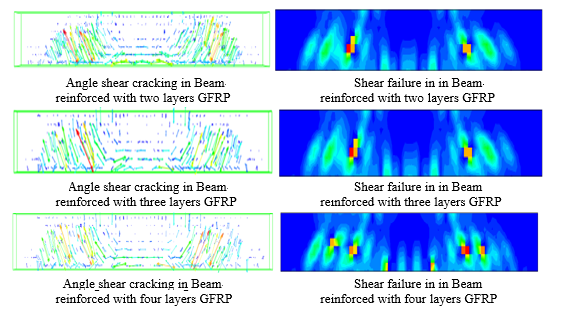
tension micro cracks and shear cracks occurred under loading point and supporting. Also, shear cracking in GFRP composites sheets with variable layers.
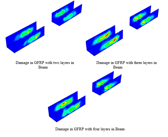
Damage in GFRP composites sheets due to the severity of the load occurred in the direction of beam damage. The greatest amount of damage occurred in the area where there is the largest plastic strain. After strengthen two-layer of GFRP, the intensity of load and strain of plastic materials is the cracking beams for shear.
In mid-span the bending and vertical cracks have been created but in the area between the supporting to the severity of loading, cracking occurred as shear and inclined. Damage in GFRP composites sheets created along cracking in concrete beam
total seven specimens reinforced with GFRP and the shear behavior of reinforced concrete, load-displacement relationship, mode of shear failure, effect of increasing GFRP layer and damage mode in GFRP sheets studied. Based on the result of the test, the following conclusion are drawn:
- Using finite element method software as ABAQUS, can be seen cracking in concrete beam under GFRP composites sheets.
- Damage in GFRP composites sheets occurred along to beam shear cracking as inclined.
- Reinforced composite beam to a 45-degree angle just want a better effect on shear capacity and behavior towards the use of composite beam angle of 90-degrees.
- By increasing the number layers of GFRP composites sheets, shear cracking and fracture was improved and shear capacity was more increased.
- 5)Use continuous GFRP composites sheets increased shear capacity significantly, because cover all crack and improve the shear behavior. For example, Beam-5 reinforced with 4-layers of GFRP sheets, shear capacity increases to 95 percent.
Seismic behavior of concrete elevated tanks
The elevated tanks are important structures filled with large volume of water for using at critical time. these structures are made with steel and concrete material. in tanks under lateral load as earthquake, the structural responses like maximum displacement, base shear and overturning may get exacerbated due to sloshing of water in reservoir. Seismic response of liquid storage tanks is quite different from conventional structures not only due to hydrodynamic effects acting on the tank shell but also owing to many sources of nonlinear behavior mechanisms of tanks such as buckling of the tank shell, large amplitude nonlinear sloshing, nonlinear tank–soil interaction, material yielding, plastic rotation of base plate and successive contact and separation between tank base and soil. For the assessment of earthquake response of such structures, numerical methods are indispensable tools since they offer a concise way of accurately considering all these nonlinearities in the same model. Yet, before using numerical techniques for design purposes for the evaluation of different configurations of the fluid–tank systems when subjected to several earthquakes ground motions.
The estimation of the potential degree of risk of tank failure during an earthquake is a very difficult task since the liquid–tank system possesses many different nonlinear behavior mechanisms which may be triggered simultaneously or independently depending on the several factors, such as, characteristics of earthquake, contained liquid properties and its depth, dimensions of the tank, roof type, material properties and supporting conditions and stiffness of underlying soil medium. These nonlinear behavior mechanisms can emerge in the form of elastic-plastic (elephant foot) and elastic (diamond shape) buckling of the tank wall, rupture of junction between tank wall and base, roof damage, tank support system and foundation failure and breaking of anchor bolts when tank is subjected to seismic motions. In addition to them, successive contact and separation between base plate and foundation due to uplift of tank base, which is more pronounced for unanchored tanks, may induce plastic rotations at the junction of base plate– shell and plastic yielding in the base plate.
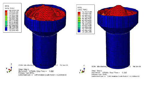
The elevated tank could be modeled using finite element modeling or simplified model. in finite element modeling, the reservoir and fluid model. in two follow Figure, the concrete elevated tank using in my research modeled in ABAQUS software is shown.
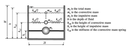
In simplified elevated tank modeling, the fluid was modeled by using two elements, the effect of weight was modeled using concentrate mass linked by rigid element and the effect of water sloshing was modeled using another concentrate mass linked by Springs as shown in follow Figure.
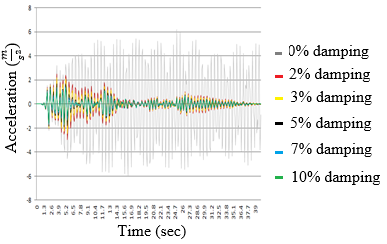
The important result of this study shown that Structural damping rate has no significant effect on structural responses. in the following Figure the effect of damping ratio on maximum displacement under Imperial Valley earthquake is shown.
Seismic Behavior of Semi-Supported Steel Shear Wall System
Un-stiffness Steel Shear Wall is a lateral resistant system which has shown great performance during recent earthquakes as well as in laboratory tests. Semi-supported steel shear wall is a special kind of unstiffened steel shear wall which is a quite new one with many unknown aspects. Seismic parameters are among the most important unknown aspects of this system.
In recent years, due to urban development and growth of construction in the country, attention to the earthquake is highly important, and to moderate the lateral forces, various lateral-load-resisting systems are used. Each of these systems has unique characteristics. Selecting the type of lateral force resisting system depends on load combination, the structural behavior, how to conduct a gravity load, and architectural design. In addition, the selection of a lateral load resisting system depends on geometry sizes of the structure, regular limitations, the amount of lateral force, maximum displacement, etc. The main objective of seismic design of structures is that structural behavior must stay in the linear range and no damage against forces of minor earthquakes, and while maintaining the overall stability, tolerates structural and non-structural damages against severe forces. In severe earthquakes, the structure usually shows inelastic behavior and an inelastic analysis is needed to design them.
Until a few decades ago, there was no concepts such structural behavior factor, and for seismic design of structures, a percent of the weight of the structure was applied to the building as horizontal load equivalent to seismic load, and the building was designed for that load. In recent decades, in order to modify the base shear force and taking into account the parameters that impact on seismic force, other factors are added, and these factors are directly multiplied together and the necessary adjustments are made. In codes, these factors are obtained based on engineering judgment and experimental observations for various structural systems, which ultimately determines the behavior factor. A steel shear wall has good performance in reducing the structural responses. Several studies have been conducted in this area including research by Driver et al.
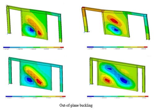
Out-of-plane displacement of steel plate is of high importance, since first, it destroys joinery and secondly it may cause damage to connections between the plate and the channels (UNPs). In studying Out-of-plane displacement of steel plate, results shows that by decreasing length and increasing thickness of the plate, displacement also reduces. However, decreasing length and increasing thickness , out-of-plane displacement of steel plate and its boundary components approach, where the plate is caused such a buckle.
According to studies, the following results can be achieved.
• In the case of keeping the horizontal cross-sectional area of steel plate, by increasing length (the wall thickness should be reduced for a constant cross-sectional area), the structure yields at smaller displacement. So, in this situation, steel plate shear wall has higher ductility. With a 50 percent increase of length of the steel plate, ductility factor increases 13%, and energy absorption of the structure increases about 5%.
• Although in all the models the yield onset starts from base of the structure, by increasing length, the yield onset of models moves to the top of the structure and rises on a wider surface.
• With 50% increase of thickness, in addition to improving in the energy absorption of the system between 21 to 26%, the stiffness and the shear strength of the system also increases. The increased thickness increases the stiffness between 26 to 34%, and increases the shear strength to higher than 22%. Also, increased thickness of steel plate, improves behavior factor of the system between 6 and 10 percent.
|


